Electrical systems rarely fail without warning — the problem is, those warning signs are often invisible. Overheating connections, overloaded circuits, and failing components can go unnoticed until they lead to costly downtime or even safety incidents.
That’s where thermal imaging becomes extremely useful. Instead of guessing or relying only on manual checks, technicians can quickly “see” temperature differences and identify problems early.
Why Electrical Systems Require Thermal Inspection
In industrial environments, electrical equipment operates under continuous load. Over time, this creates stress on components such as cables, terminals, and breakers.
Common issues include:
- Loose or corroded connections
- Overloaded circuits
- Phase imbalance
- Aging components
These problems don’t always show visible signs at first. A system may still be running, but internally, temperatures are rising.
Thermal inspection allows you to detect these abnormal heat patterns before they turn into failures.
Common Electrical Faults Detected by Thermal Imaging
One of the biggest advantages of thermal cameras is how quickly they reveal hidden faults.
These are issues that traditional inspection methods might miss, especially during routine checks.
For example:
- Loose terminals often appear as localized hot spots
- Overloaded circuits show higher temperatures compared to normal lines
- Unbalanced loads can be identified by uneven heat distribution
- Worn or failing components gradually heat up over time
How Thermal Imaging Improves Inspection Efficiency
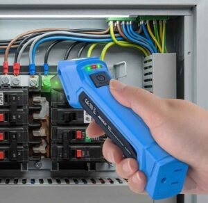
Compared to traditional tools, thermal imaging makes electrical inspection faster and safer.
- It’s non-contact, so there’s no need to touch live components
- Inspections can be done without shutting down equipment
- Results are instant and visual, making it easier to identify problems
If you’re still deciding between tools, it’s worth understanding the difference between a thermal camera vs infrared thermometer — one gives you a full picture, the other only a single point reading.
For teams handling multiple panels or large systems, that difference matters a lot.
Step-by-Step Electrical Inspection Process
A typical thermal inspection is straightforward, but consistency is key.
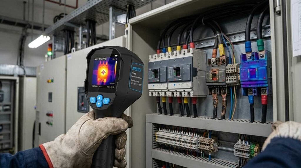
- Scan electrical panels while the system is under normal load
- Look for abnormal heat patterns or temperature differences
- Capture thermal images for documentation
- Compare similar components to spot inconsistencies
- Record and analyze findings for maintenance planning
Even for technicians new to this method, the learning curve is relatively low. If needed, you can first learn about what a thermal imaging camera is to grasp its basic principles before applying it in the field.
Key Benefits for Industrial Applications
Thermal imaging is not just about finding problems — it’s about preventing them.
In industrial settings, this translates directly into business value:
- Reduced unplanned downtime
- Lower maintenance costs
- Improved safety for personnel
- Better planning for repairs and replacements
Instead of reacting to failures, companies can move toward a more predictive maintenance approach.
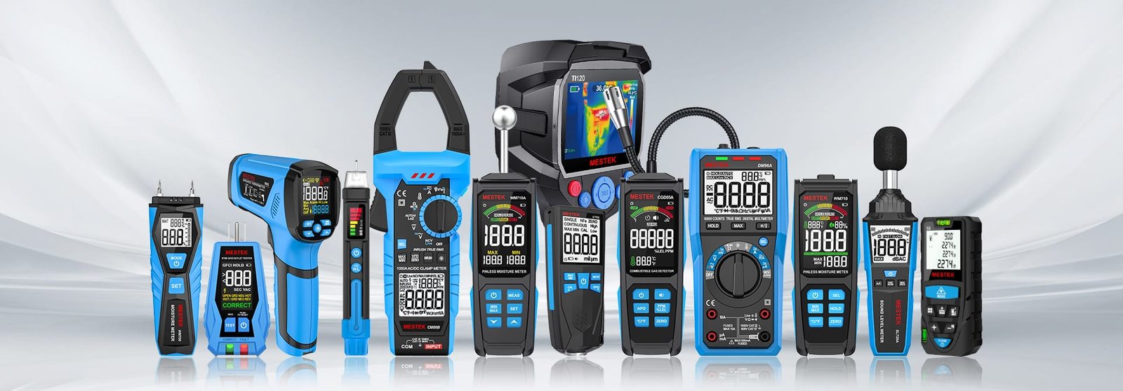
Choosing the Right Thermal Camera for Electrical Inspection
Not all thermal cameras are the same, especially when it comes to electrical applications. You don’t always need the most expensive model, but you do need one that’s reliable and clear enough for real-world inspection.
Here are a few practical things to look for:
- Resolution – higher resolution helps detect smaller hotspots
- Temperature range – should cover typical electrical operating conditions
- Thermal sensitivity (NETD) – important for identifying subtle differences
Recommended Thermal Camera for Electrical Inspection
For day-to-day industrial use, a balance between performance and usability is often more important than having the highest specs.
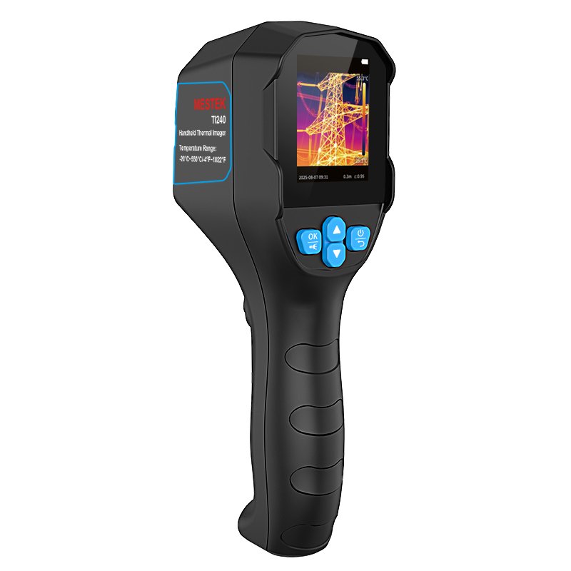
The MESTEK TI240 Thermal Imaging Camera is designed with this in mind.
With a 240×240 resolution, it provides enough detail to identify hotspots in electrical panels without overcomplicating the workflow. Its sensitivity allows technicians to catch early-stage temperature differences, which is critical for preventive maintenance.
At the same time, the handheld design makes it practical for routine inspections across different locations, especially when speed and convenience matter.
Conclusion
Electrical faults rarely happen suddenly — they build up over time. The challenge is catching them early enough.
Thermal imaging gives you a clear advantage by turning invisible heat into visible data. Whether it’s part of routine maintenance or a targeted inspection, it helps teams work faster, safer, and more efficiently.
For industrial environments where downtime is costly, that kind of visibility isn’t just helpful — it’s essential.