In modern electronics testing and development, power supply control is no longer limited to manual adjustment. As systems become more complex, engineers and technicians need more precise and repeatable ways to manage voltage and current.
This is where a programmable DC power supply becomes useful. It allows users to control output settings digitally, making testing more efficient and consistent.
What Is a Programmable DC Power Supply
A programmable DC power supply is a regulated power source that can be controlled through external interfaces such as USB, RS232, or RS485.
Unlike traditional bench power supplies that rely on knobs and manual settings, programmable models allow users to set voltage and current through software or automated commands.
This means the same test conditions can be repeated accurately, which is especially important in product testing and development.
Working principle of programmable DC power supply
The basic function is still the same as any DC power supply: it converts AC input into a stable DC output.
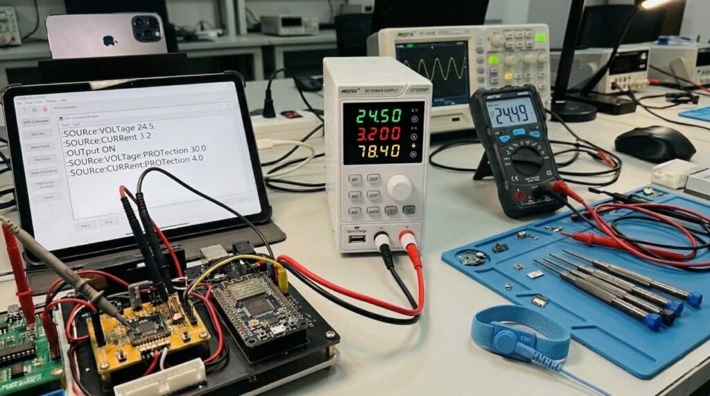
The key difference lies in how the output is controlled. Instead of adjusting values manually, users can send commands from a computer or control system. These commands define:
- Output voltage
- Output current
- Protection limits (OVP/OCP)
- On/off status
The power supply receives these instructions through its communication interface and adjusts its output in real time.In simple terms, it acts as a controllable power source that can follow predefined settings without manual intervention.
Key Features of Programmable Power Supplies
Even entry-level programmable models usually include several useful features:
- Remote control via USB or serial communication
- High stability output for consistent testing
- OVP and OCP protection to prevent damage
- Preset or memory functions for quick setup
These features make it easier to perform repeated tests and reduce human error during operation.
Common Applications
Programmable DC power supplies are widely used in both lab and light industrial environments.
Some common use cases include:
- Electronics testing – powering circuits and PCBs during development
- Product validation – simulating different voltage conditions
- Automated testing setups – integrating with basic control systems
- Educational labs – teaching power control and testing methods
For applications that require simple automation or remote operation, even a low-power programmable unit can significantly improve efficiency.
Why Use a Programmable Power Supply Instead of a Manual One
Manual power supplies work well for basic tasks, but they have limitations when consistency and efficiency matter.
A programmable unit offers several advantages:
- Faster setup through software control
- Repeatable test conditions
- Reduced manual adjustment errors
- Easier integration into testing workflows
For users handling multiple tests or batch verification, these benefits quickly become noticeable.
Select a suitable programmable power supply

When selecting a programmable DC power supply, it’s important to match the specifications to your application.
Key factors to consider include:
- Output voltage and current range
- Communication interface (USB, RS232, RS485)
- Stability and accuracy
- Ease of control and setup
For most entry-level testing tasks, a compact model with basic remote control capability is often sufficient.
Conclusion
A programmable DC power supply is a practical tool for anyone who needs controlled, repeatable power output. By allowing remote adjustment and simple automation, it helps streamline testing processes and improve accuracy.
Whether used in electronics development, product testing, or lab environments, it offers a clear step forward compared to traditional manual power supplies — especially when consistency and efficiency are important.