Understanding the difference between line and load wires is essential for anyone working with electrical systems. Whether you are installing a switch, replacing an outlet, or troubleshooting a circuit, correctly identifying line and load wires helps prevent electrical hazards, equipment damage, and wiring errors.
What Are Line and Load Wires
Before identifying wires, it is important to understand their roles in an electrical circuit.
What Is a Line Wire?
The line wire carries electrical power from the power source (such as a breaker panel) to a device. It is the incoming energized conductor that supplies voltage to switches, outlets, or appliances.
Key characteristics of a line wire:
- Usually always energized when the circuit is on
- Delivers power from the electrical panel
- Often referred to as the “hot” wire
What Is a Load Wire?
The load wire carries electrical power from a switch or control device to the electrical load, such as a light fixture, outlet, or appliance.
Important points about load wires:
- Only energized when the controlling device is turned on
- Supplies power to the downstream device
- Typically another section of the hot conductor
Line vs Load: What’s the Difference?
Although both wires can carry voltage, their functions are different. Understanding this distinction is critical for safe wiring and proper device operation.
| Feature | Line Wire | Load Wire |
| Function | Supplies power to device | Sends power to equipment |
| Location | From breaker to switch/device | From switch to load |
| Voltage presence | Always energized | Energized only when switched on |
| Wire type | Hot wire | Usually hot wire |
Why Correct Identification Matters
Incorrectly wiring line and load conductors can cause:
- Switches that do not turn devices off completely
- GFCI outlets that fail to provide protection
- Electrical shock hazards
- Damage to connected equipment
Many modern devices, including smart switches and GFCI outlets, will not function correctly if line and load are reversed.
Common Wire Color Codes (But Don’t Rely on Them Alone)
Wire colors can offer clues, but they are not guaranteed.
Typical color conventions:
- Line / Hot: Black, red, or brown
- Neutral: White or gray
- Ground: Green or bare copper
Color codes vary by region and installation age. Always verify using proper testing methods.
How to Identify Line and Load Wires Safely
1. Turn Off Power Before Inspection
Always shut off the circuit breaker before touching any wires. Use a voltage tester to confirm that no voltage is present before handling conductors.
2. Identify the Power Source Location
The wire coming directly from the breaker panel is typically the line wire, while the wire leading to a fixture or outlet is usually the load wire.
However, physical routing alone is not always reliable—testing is still required.
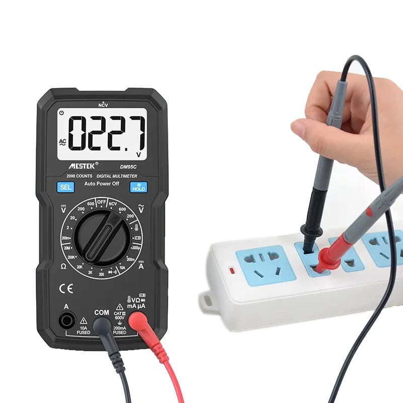
3. Use a Non-Contact Voltage Tester

A non-contact voltage tester can help identify the energized wire.
- Turn the breaker back on
- Test each wire individually
- The wire that shows voltage regardless of switch position is likely the line wire
This method is quick but not precise for complex circuits.
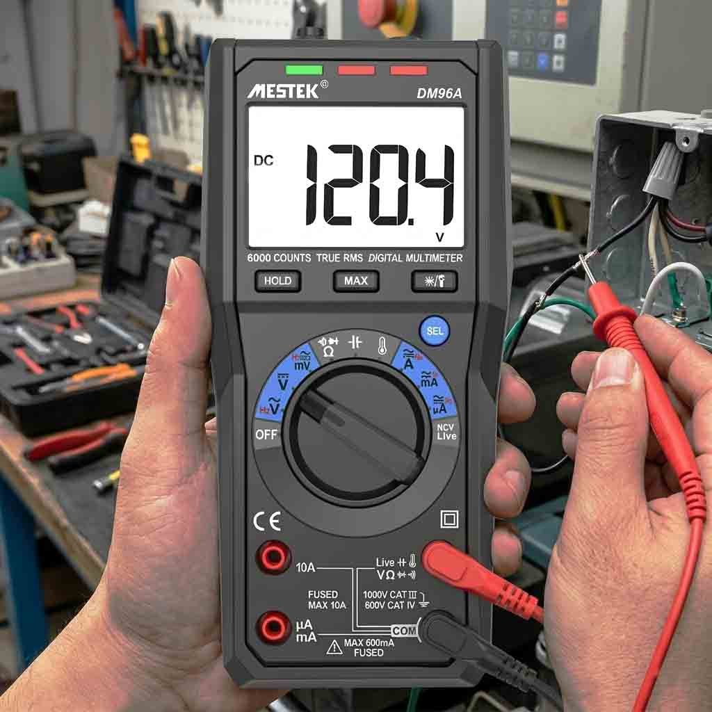
4. Use a Multimeter for Accurate Identification
A multimeter provides the most reliable results.
- Set the multimeter to AC voltage
- Measure voltage between each wire and ground
- The wire showing full voltage when the switch is off is the line
- The wire showing voltage only when the switch is on is the load
This method is highly recommended for professional and DIY electrical work.
How to Identify Line and Load on a Switch
In a standard switch installation:
- Line wire connects to the power feed
- Load wire connects to the switched device
Some switches label terminals as “LINE” and “LOAD,” but older models may not.
Tip: If the switch controls a light, the wire that becomes energized only when the switch is on is the load wire.
Identifying Line and Load on GFCI Outlets
GFCI outlets are especially sensitive to line and load placement.
- LINE terminals receive power from the breaker
- LOAD terminals supply downstream outlets
Reversing these connections will prevent the GFCI from resetting or providing protection.
Always follow manufacturer markings and verify with a voltage tester.
Is Neutral the Same as Load?
No. Neutral wires are not load wires.
Neutral wires:
- Complete the circuit by returning current to the source
- Are typically white or gray
- Do not supply power to devices
Load wires usually carry voltage and should never be treated as neutral conductors.
Common Mistakes When Identifying Line and Load
- Assuming wire function based only on color
- Forgetting to turn off the breaker before testing
- Confusing neutral wires with load wires
- Testing multiple wires together instead of individually
Careful testing prevents dangerous assumptions.
Tools Recommended for Identifying Line and Load Wires
- Non-contact voltage tester
- Digital multimeter
- Insulated tools
- Proper personal protective equipment
Reliable tools reduce the risk of misidentification and injury.
Safety Tips for Electrical Work
- Always turn off power before touching wires
- Test wires even after shutting off breakers
- Work in a dry environment
- When unsure, consult a licensed electrician
Frequently Asked Questions
Can line and load wires be the same color?
Yes. Color alone is not a reliable indicator. Always test.
What happens if line and load are reversed?
Devices may malfunction, and safety features like GFCI protection may fail.
Can I identify line and load without tools?
In rare cases, but tools are strongly recommended for accuracy and safety.
Final Thoughts
Knowing how to identify line and load wires is a fundamental electrical skill. By understanding their functions and using proper testing methods, you can work more safely and ensure electrical devices operate correctly.