Thermal cameras help inspectors see abnormal heat in energized electrical equipment without touching the target. This makes them useful for checking panels, breakers, terminals, cables, and connections while systems operate under load. The electrical hot spots indicate that one area is warmer than expected. It is not automatically a confirmed fault. Compare the results with similar components, then follow up with appropriate electrical testing, visual inspection, and safe corrective work. Used properly, thermal imaging can help teams find developing problems before they cause downtime or equipment damage.
What Causes Hot Spots?
Electrical hot spots usually appear when current creates more heat in one area than the system should produce. Common causes include:
- Loose or corroded connections: A loose or corroded terminal can increase resistance at the contact point. As current passes through it, the area may heat up. This heat can damage insulation and make the connection worse over time. A warm terminal is more significant when nearby terminals carrying a similar load remain cooler.
- Overloaded circuits: A circuit carrying more current than it was designed for can heat its conductors and connection points. The pattern may extend along a cable, busbar, breaker, or termination. Thermal imaging cannot confirm current, so use an appropriate meter to verify the load.
- Unbalanced loads: In a three phase system, one phase may carry more current than the others. That phase can appear warmer when all phases are viewed under similar conditions. Compare the phases, then investigate with current and voltage measurements.
- Faulty electrical components: Breakers, fuse holders, contactors, relays, motor connections, and other components can develop increased resistance or poor electrical contact. Heat may appear at one terminal, on one side of the component, or across its body. Testing is needed to identify the exact cause.
Other conditions can also affect readings. Ambient temperature, ventilation, sunlight, installation design, and differences in load can make one component appear warmer than another. That is why context matters during electrical hot spot detection.
How to Find Them With a Thermal Camera
A systematic approach to thermal camera electrical inspection ensures you don’t miss critical issues and that the data is accurate for future comparison. Use a repeatable process:
Inspect Equipment Under Normal Operating Load
Ideally, conduct thermal inspections when the system is at steady state and under at least 40% of its typical operating load. Heat generated by resistance rises with the square of the load (P=I²R), so problems are much easier to detect when the system is working. If the load is too low, the temperature rise might be too subtle for the camera to distinguish from the background.
Scan Key Components
The inspection should cover all electrical panels and high load connection points, including breakers, terminals, drives, disconnects, and controls. Technicians should open enclosures whenever possible, as infrared cameras cannot see through solid metal or plastic cabinets. If a hot spot is visible on the exterior of a cabinet, the internal temperature is likely significantly higher.
Compare Similar Components
A core principle of thermal imaging electrical inspection is the “comparison method.” By viewing three phases side by side, you can easily spot anomalies. Under equal load, similar components should exhibit equal temperatures. If one phase is significantly warmer than the others, it indicates an imbalance or a bad connection.
Look at the Thermal Pattern
Effective detection involves looking at the thermal pattern rather than just the hottest single point. A localized hot spot at a terminal suggests a loose wire, while a uniform heat signature along an entire cable suggests an overload. Capturing these patterns helps technicians understand the nature of the problem before they even pick up a screwdriver.
Record Findings
Documentation is essential. Using software to save thermal images alongside digital photos of the equipment creates a baseline. This enables long term tracking and helps verify successful repairs during the next re-scan.
How to Interpret a Thermal Hot Spot
Interpreting the results of a thermal imaging electrical inspection requires distinguishing between “normal” heat and “abnormal” conditions. Every electrical circuit generates some heat, but the way that heat is distributed provides the clues needed for a diagnosis.
For instance, a point source hot spot at a terminal lug typically indicates high resistance due to a loose screw or corrosion. In contrast, heat concentrated near the center of a fuse may indicate that it is operating close to its rated capacity or has developed internal deterioration. If a transformer shows heat at the cooling fins, it might be working correctly. However, if the heat is unevenly distributed across the tank, there may be an internal winding issue.
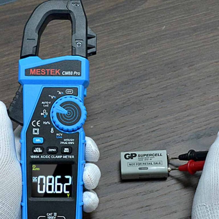
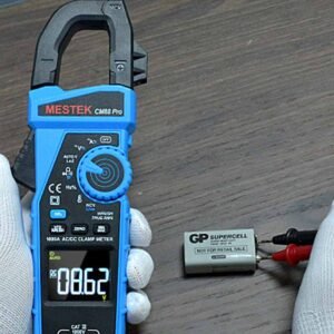
Remember: a thermal camera shows where the problem is, but it doesn’t always tell you what the problem is. Thermal imaging identifies abnormal conditions. But additional electrical testing, such as using a clamp meter to check current or a micro ohmmeter to check contact resistance. This is often necessary to determine the actual cause and confirm the repair strategy.
Common Mistakes When Inspecting Hot Spots
Several simple mistakes can produce misleading results:
- Inspecting without enough load: A circuit may look normal when idle. When safe, inspect during representative operation.
- Relying only on color: Red or white does not automatically mean danger. The color scale can change with the selected temperature span. Use measured temperatures and comparisons.
- Ignoring similar components: Without a baseline, it is hard to tell whether a reading is unusual. Compare matching phases and components.
- Measuring reflective metal incorrectly: Shiny metal can reflect nearby heat and produce an unreliable reading. Change the viewing angle and use a suitable reference point.
- Treating the scan as the repair: Finding abnormal heat begins the workflow. You still need to confirm the cause, correct it, and check again.
Choosing a Thermal Camera for Electrical Inspection
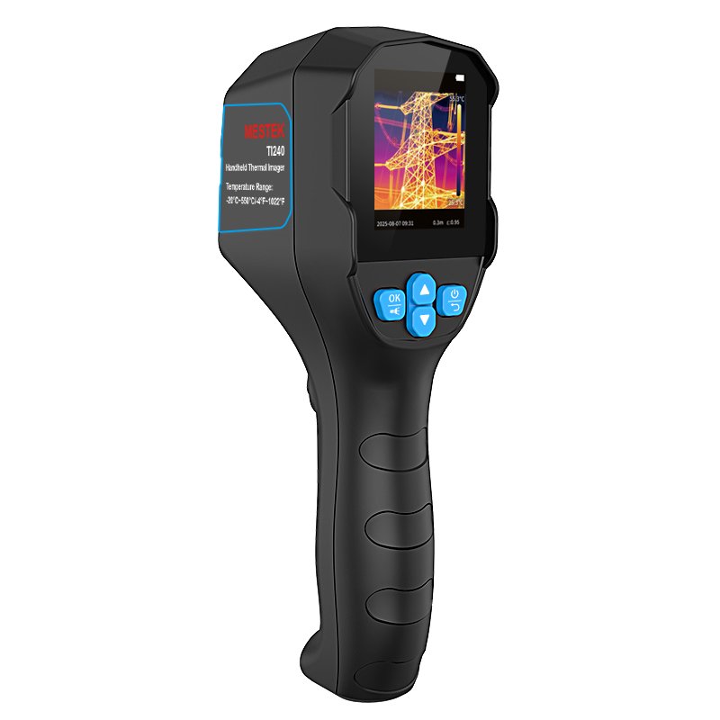
For electrical work, focus on the specifications that affect detection, measurement, and documentation:
- IR resolution: Higher resolution shows more detail and helps separate nearby terminals, connectors, and small components. A 240 × 240 pixel sensor provides more detail than a lower resolution sensor.
- Thermal sensitivity (NETD): A lower NETD helps detect smaller temperature differences when heating is subtle.
- Temperature range: Choose a range covering the equipment and conditions you expect to inspect.
- Point and area temperature measurement: Point measurements check a terminal or component. Area measurements show how heat spreads.
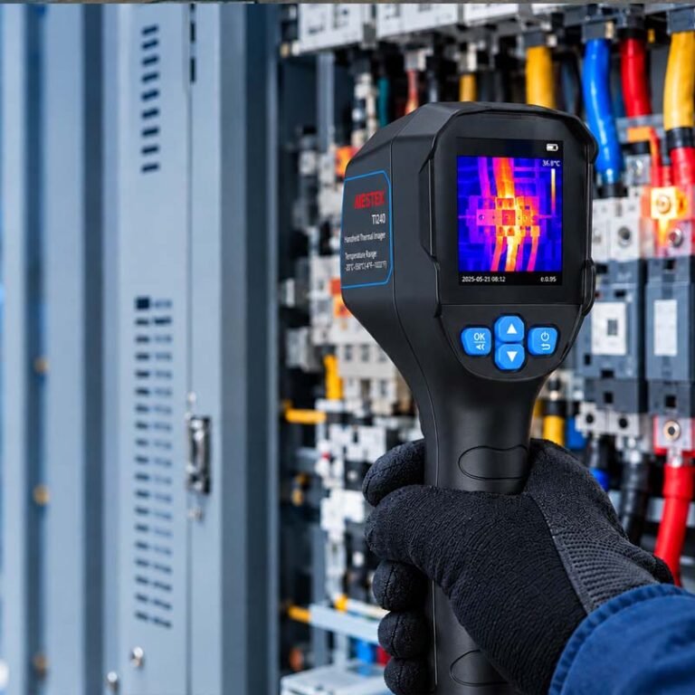
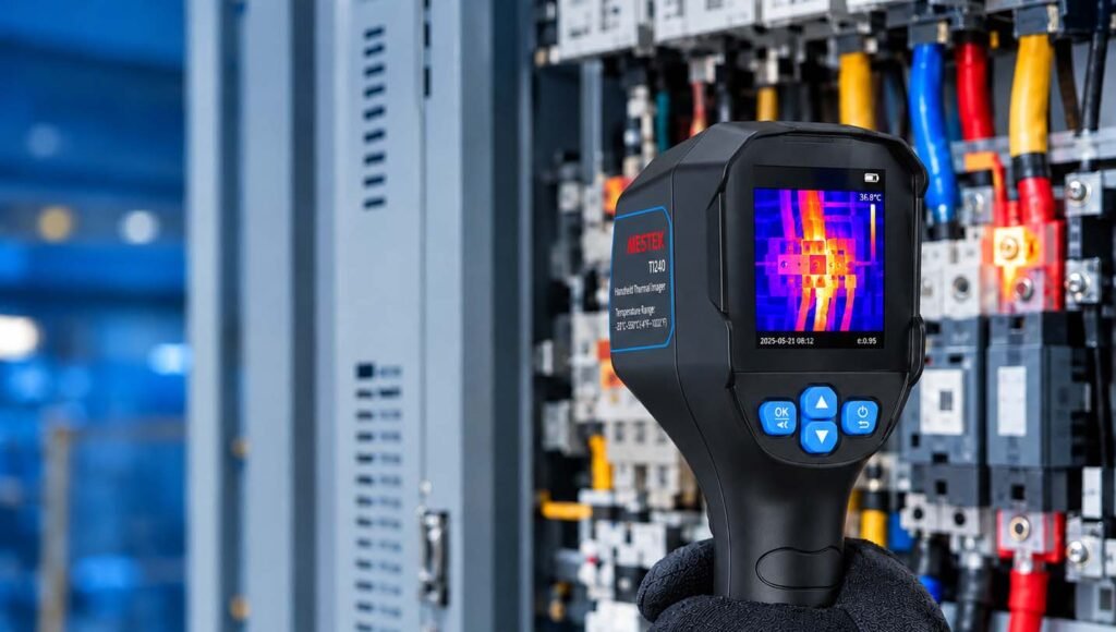
The MESTEK TI240 is an example of a thermal camera designed for these inspection requirements. It offers 240 × 240 IR resolution and a wide 50° field of view. This allows technicians to inspect large electrical equipment more efficiently. Its thermal sensitivity of less than 60mK and measurement range of -20°C to 550°C support inspections across a broad range of operating conditions.
The TI240 also offers automatic high and low temperature capture and a stated accuracy of ±2°C or ±2%, whichever is greater. These features support practical thermal imaging electrical inspections, but users should follow the camera manual and site procedures.
What to Do After Finding a Hot Spot
Finding a hot spot is only the first part of the inspection. A complete maintenance workflow should include the following steps:
- Find: Use the thermal camera to locate the abnormal thermal pattern.
- Compare: Verify the delta-T against similar components or historical inspection data.
- Investigate: Perform appropriate secondary tests, such as current, voltage, or resistance measurements, to help identify the root cause.
- Repair: Correct the identified issue by tightening connections, replacing faulty components, redistributing loads, or taking other appropriate corrective action.
- Re-scan: After the repair, return the system to normal operating load and scan it again to confirm that the abnormal thermal condition has been resolved.
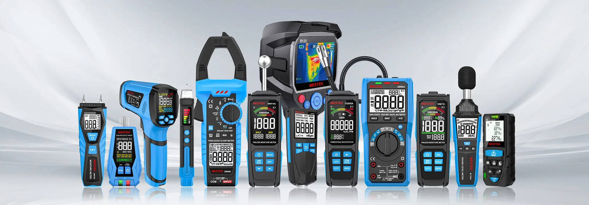
Explore the MESTEK thermal imaging camera range to support repeatable electrical inspection and maintenance work.
Conclusion
Finding electrical hot spots with a thermal camera is not about chasing the hottest color on the screen. The most useful inspection combines normal operating load, careful scanning, comparison between similar components, thermal pattern interpretation, accurate measurement, and documented follow up. A hot spot is a warning sign that helps direct attention. Confirm the cause with suitable electrical tests, repair the underlying problem safely, and re-scan to verify the result.