Clamp meter is an electrical testing instrument designed to measure current by clamping around a conductor. Unlike traditional current measurement methods that require the circuit to be opened, a clamp meter allows non-contact current measurement, improving safety and efficiency.
Modern clamp meters often combine multiple functions into one device, working not only as a clamp meter tester, but also as a voltage tester, resistance meter, and continuity tester. Many models support both AC and DC measurements, making them suitable for a wide range of applications.
How does the clamp meter work?
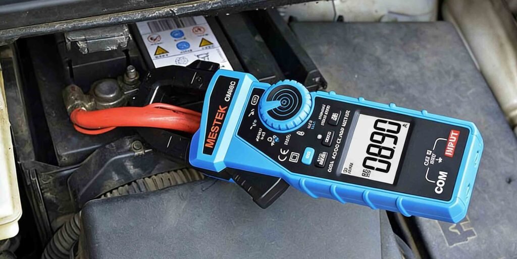
For DC current measurement, most AC DC clamp meters use a Hall effect sensor. When DC current flows through a conductor, it generates a magnetic field. The Hall sensor inside the clamp detects this magnetic field and converts it into an electrical signal, which is then displayed as a current value on the screen.
This technology allows the clamp meter to measure DC current accurately without direct electrical contact, which is especially useful for automotive systems, battery circuits, solar installations, and industrial DC applications.
How Does a Clamp Meter Measure DC Current?
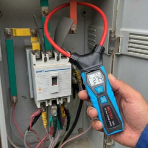
- Set the clamp meter to DC current test mode. Open the jaws to clamp a single wire. The clamp meter can only measure one wire at a time.
- Once the jaws are in place, read the current value displayed on the screen. This will be the DC current flowing through the circuit.
- If you need to measure other conductors, you should repeat steps 1 and 2 above.
- The measured current is compared with the circuit’s expected operating current to determine if it is within the normal range.
Common Clamp Meter DC Measurement Mistakes
Clamping around multiple wires at once
Forgetting to switch from AC to DC mode
Skipping the zeroing step
The measured current is below the minimum resolution of the clamp meter.
Holding the clamp at an angle instead of straight
requently Asked Questions About Clamp Meters
Can all clamp meters measure DC current?
No. Only clamp meters equipped with a Hall effect sensor can measure DC current. Always check whether your clamp meter supports DC measurement before use.
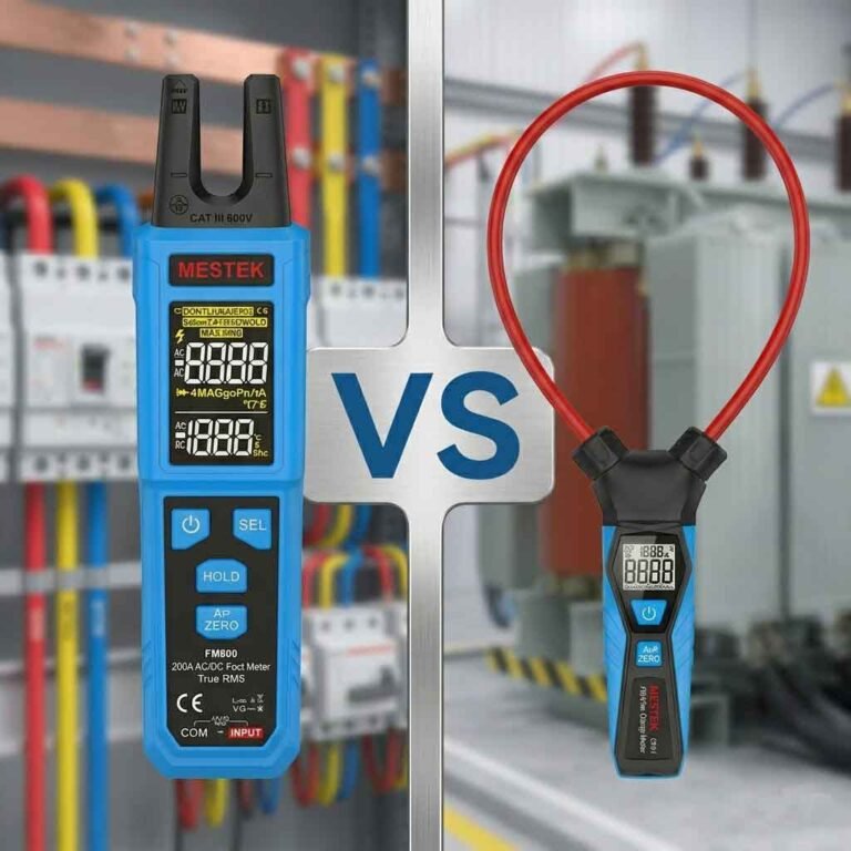
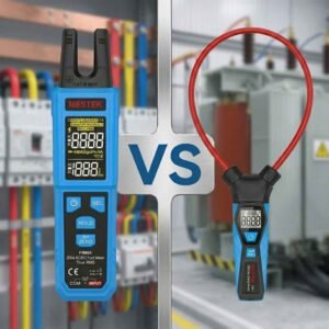
What is the difference between an AC clamp meter and an AC DC clamp meter?
An AC clamp meter measures alternating current only. An AC DC clamp meter can measure both alternating and direct current, making it more versatile for different applications.
Is a clamp meter safer than a traditional multimeter?
Yes. Because a clamp meter does not require direct contact with live conductors, it reduces the risk of electric shock and accidental short circuits.
Can a clamp meter measure voltage?
Many modern clamp meters also function as a clamp voltage meter, allowing users to measure AC and DC voltage using test leads in addition to current measurement.
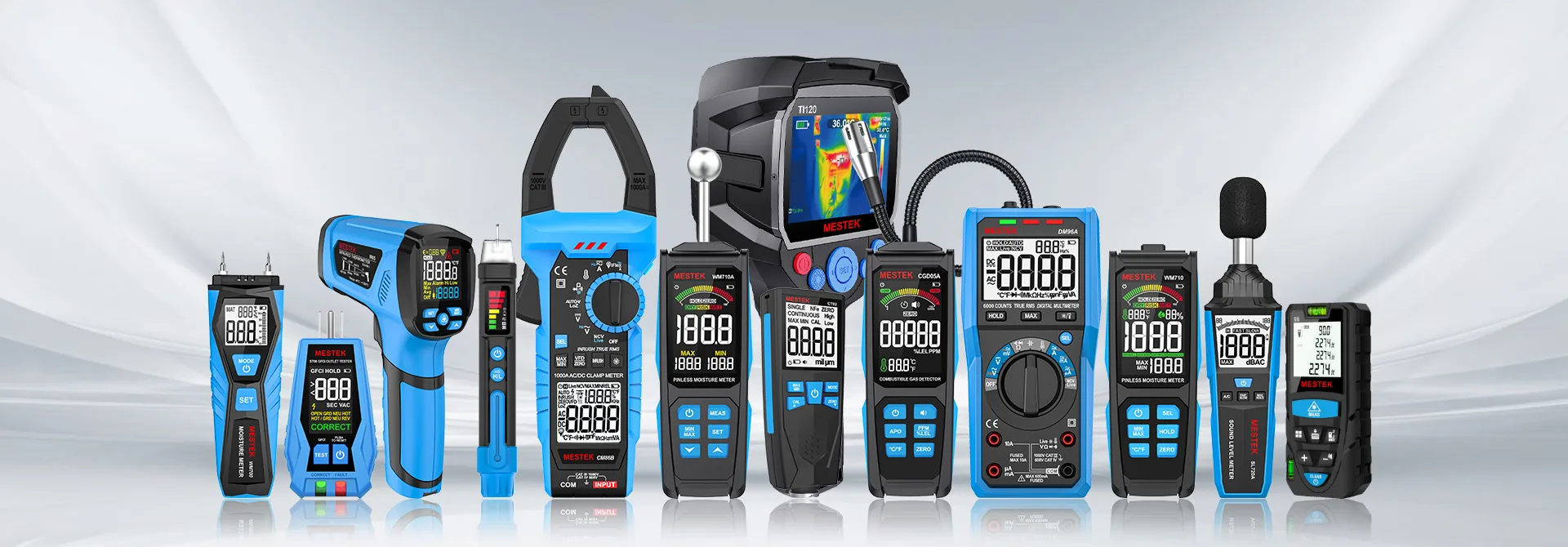
Common Features of a Digital Clamp Meter
A modern digital clamp meter typically includes multiple measurement and safety features, such as:
- AC and DC current measurement
- AC and DC voltage measurement
- Resistance and continuity testing
- Auto-ranging function
- Data hold and backlight display
- Overload protection
- Compact and ergonomic design
These features make clamp meters essential tools for electricians, technicians, and maintenance professionals.
Conclusion
Learning how to measure DC current with a clamp meter is an essential skill for working with modern electrical systems. Thanks to Hall effect technology, today’s clamp meters allow safe, fast, and accurate DC current measurement without interrupting the circuit.
By understanding how a clamp meter works and following proper measurement steps, you can confidently use a clamp meter tester to diagnose and monitor DC electrical systems in a wide range of applications.