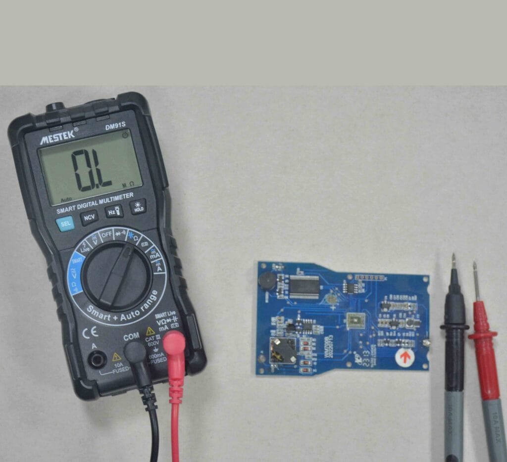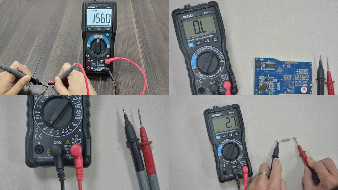
If your computer suddenly stops turning on or behaves erratically, your motherboard could be the culprit. But how do you know for sure? The best way to test a motherboard with a multimeter is by checking the power supply, capacitors, and short circuits on the board.
Why You Should Test Your Motherboard
The motherboard acts as the backbone of your computer. Every critical component — CPU, RAM, GPU, and storage — depends on it for power and communication.
Common signs of motherboard failure include:
The computer won’t boot or power on
Random freezes or restarts
Burning smell or visible damage
Beeping sounds during startup
Before replacing your motherboard, it’s smart to check the motherboard with a multimeter. It’s quick, accurate, and saves unnecessary costs.
What You Need Before Testing
To properly test a motherboard, gather these tools:
- A digital multimeter capable of DC voltage and continuity testing
- A Phillips screwdriver
- Anti-static gloves or wrist strap
- A clean workspace with proper lighting
How can I check if there is a short circuit on the motherboard?
Disconnect the Power Supply
Safety comes first. Unplug your PC completely, and press the power button once to discharge any remaining energy.
Remove the side panel to access the motherboard. Disconnect all power connectors — especially the 24-pin ATX connector and 8-pin CPU connector — from the power supply.
Never test live circuits unless instructed. Always ensure your system is powered off during resistance and continuity checks.
Perform a Visual Inspection
Before you use your multimeter, look for visible damage such as:
- Bulging or leaking capacitors
- Burn marks around voltage regulators
- Corrosion near solder joints
A damaged capacitor can prevent proper power distribution. If you see any, note the area — you’ll test it later.
Test the Power Supply Output
Reconnect the 24-pin power connector to the motherboard and turn on the power supply (without starting the PC).
Set your multimeter to DC voltage mode and insert the black probe into a ground pin and the red probe into the +12V, +5V, and +3.3V pins.
| Voltage | Line Acceptable Range |
| +12V | 11.4V – 12.6V |
| +5V | 4.75V – 5.25V |
| +3.3V | 3.1V – 3.4V |
If any of these readings are significantly lower, your issue might not be the motherboard but the power supply itself.
Check for Short Circuits on the Motherboard
With the PC powered off and unplugged again, switch your multimeter to continuity mode.
Touch one probe to the ground pin and the other to various test points around the motherboard — particularly the power pins and MOSFETs.
- A beep or “0Ω” reading means a short circuit exists.
- No beep (open circuit) means the section is likely fine.
If you find a short, isolate the area by testing nearby capacitors, transistors, or IC chips.
Test Motherboard Capacitors
Set your multimeter to resistance (Ω) mode. Place the red probe on one leg of the capacitor and the black probe on the other.
- A healthy capacitor’s resistance should gradually increase toward infinity.
- A constant 0Ω or no change indicates a shorted or failed capacitor.
Testing capacitors is one of the best ways to check if your motherboard is working properly.
Test the CMOS Battery and Voltage Regulators
Locate the small coin-shaped CMOS battery on your motherboard. Switch your multimeter back to DC mode, place the probes across the battery terminals, and ensure it reads close to 3V.
A weak battery can cause boot errors or BIOS reset issues.
Then, test the voltage regulators (VRMs) around the CPU socket — these are responsible for stable power delivery. They should output between 1.1V–1.3V typically.
Reassemble and Verify
Once you’ve confirmed that voltages and capacitors are within normal range, reassemble your system. Reconnect all cables and power on the PC.
If the system still fails, the board may have internal damage that requires professional diagnostics or replacement.
Avoid common mistakes

- Testing with the power connected during resistance mode
- Using incorrect multimeter settings
- Forgetting to discharge static electricity
- Assuming the motherboard is faulty before checking the PSU
By avoiding these mistakes, you’ll ensure accurate results and prevent unnecessary damage.
Final Thoughts
Learning how to test a motherboard with a multimeter empowers you to diagnose hardware problems like a pro. Whether you’re troubleshooting a dead PC or verifying voltage stability, these tests help you pinpoint the issue without guesswork.
If you’re dealing with frequent hardware issues, consider reading our related guides:
How to Test a Power Supply with a Multimeter
How to Check for Short Circuits on a Circuit Board
Understanding your motherboard’s health not only saves money but also extends your computer’s lifespan.


