Measure resistance with a multimeter is one of the most common tasks. These tools are also very useful for measuring resistors and capacitors, checking for fuse replacement, and checking the continuity of a circuit. Why do we measure resistance? It’s a way to test the condition of components and circuits. As we all know, the greater the resistance, the lower the current, while the smaller the resistance, the higher the current.
What is Resistance?
Before jumping into the practical steps, let’s quickly cover what resistance is. Resistance is the opposition that a material offers to the flow of electric current, measured in ohms (Ω). Every electronic component, wire, or device has some level of resistance. By measuring it, you can confirm whether a component is working correctly or if it’s damaged.
Step 1: Prepare Your Multimeter
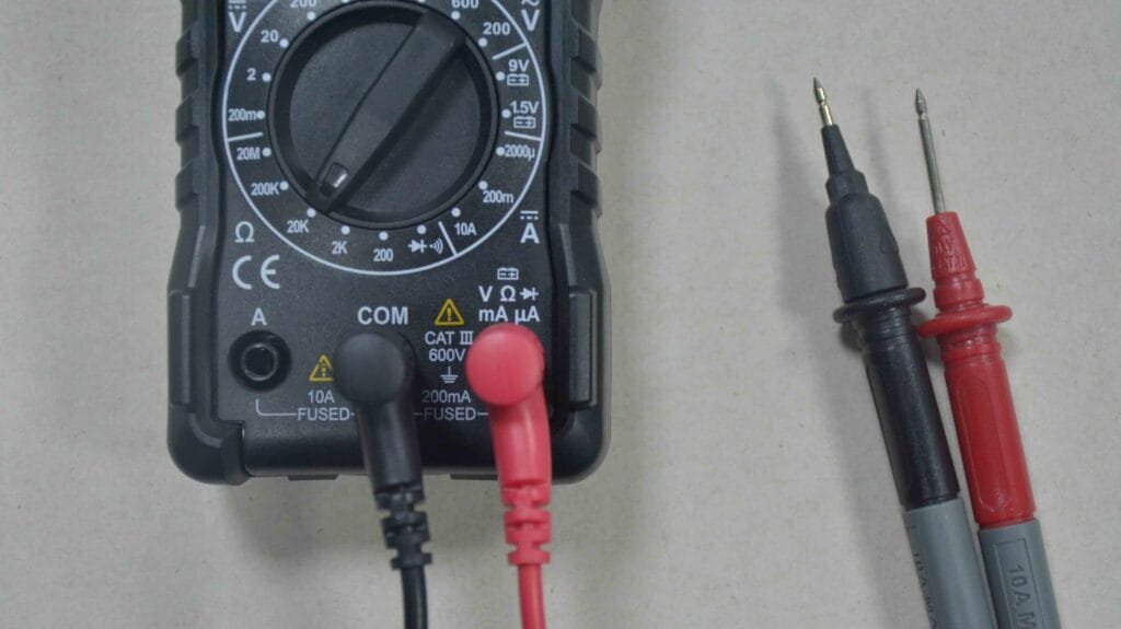
First, make sure your multimeter is ready to use. Insert the black probe into the COM port and the red probe into the port labeled “VΩmA” or similar. This setup allows you to measure resistance, voltage, and continuity.
Step 2: Set the Multimeter to the Ω Symbol
Now, turn the dial on your digital multimeter to the resistance (Ω) range. Some models have multiple ranges (e.g., 200Ω, 2kΩ, 20kΩ, 200kΩ, 2MΩ). If you’re unsure of the expected resistance value, start with the highest range and adjust downwards to ensure accuracy.
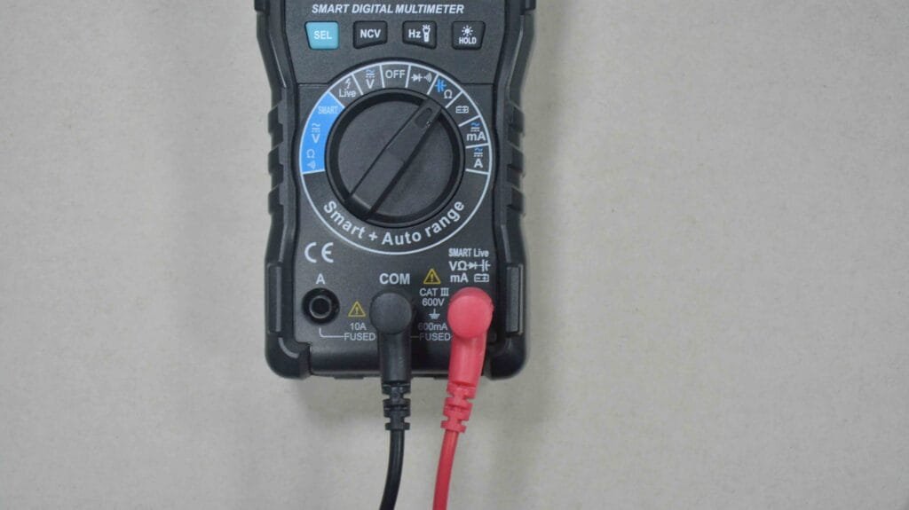
For smart or auto-ranging multimeters: Simply turn the dial to Ω mode, and the multimeter will automatically select the most appropriate range for you. [View MESTEK Smart Multimeter DM91A]
This is an important step because setting the wrong range can either give you inaccurate results or prevent the multimeter from reading at all.
Step 3: Testing a Known Resistor
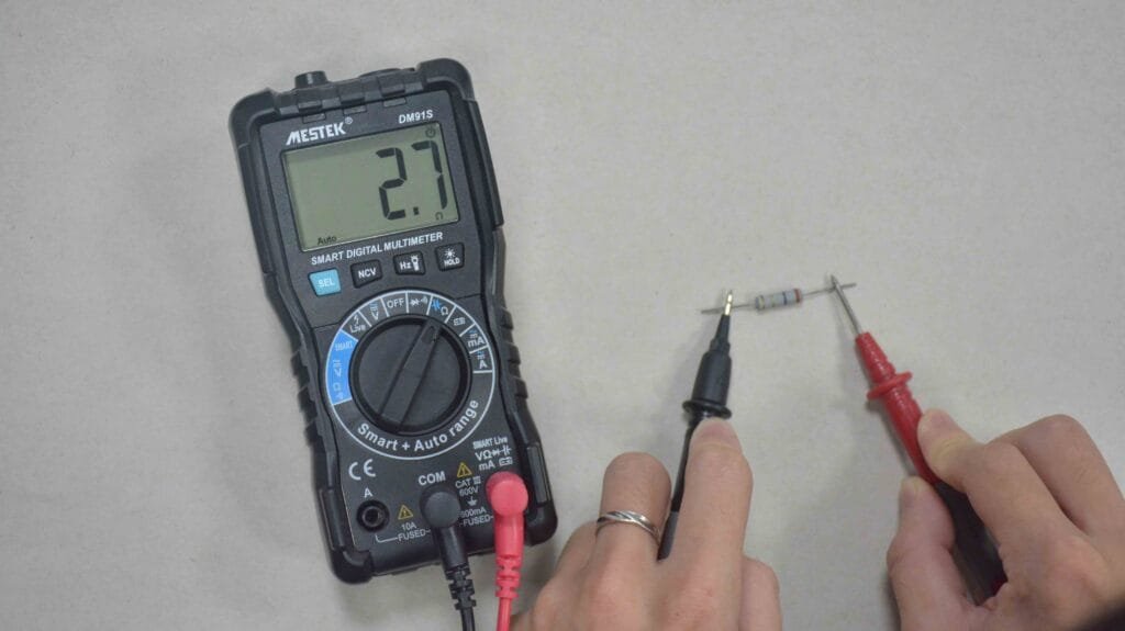
Let’s begin by testing a resistor. Hold the resistor with one hand and touch the red and black probes to each side of the component. The polarity doesn’t matter when measuring resistance, so you can place the probes in either order.
Your multimeter display should show a number followed by the Ω symbol. For example, if you are testing a 1kΩ resistor, the display might read close to 1000Ω. Keep in mind that tolerances (often ±5% or ±10%) are normal.
Step 4: Measuring Resistance in a Fuse
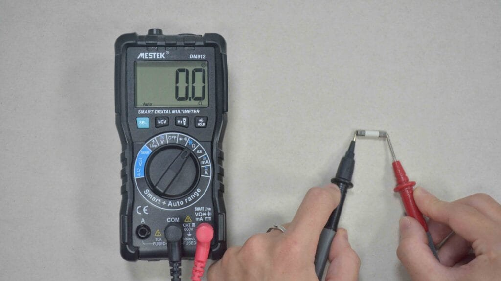
Resistance measurement is also useful for testing fuses. A healthy fuse should show nearly zero resistance (close to 0Ω). If your reading shows infinite resistance (OL on the display), it means the fuse is blown and no current can pass through it.[View Blog: how to check a fuse with a multimeter]
Step 5: Reading Ohms in Complex Circuits
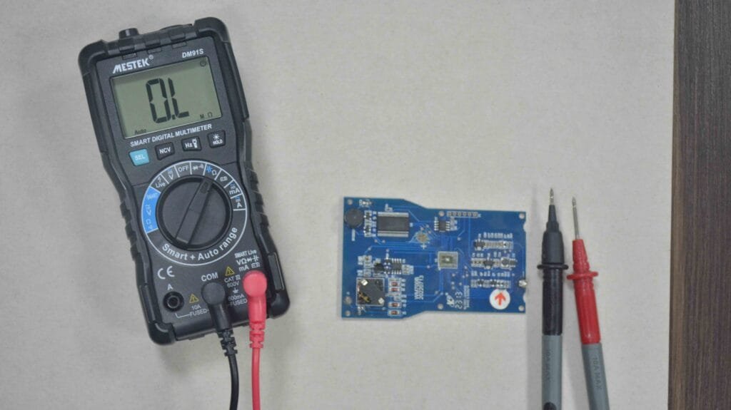
Sometimes you will measure resistance in circuits rather than individual components. For example, you might want to test a wire or connection for continuity. Touch both probes to either end of the wire. If the resistance is very low, the connection is good. If it reads OL or shows a very high resistance, the wire may be broken or corroded.
Tips for Accurate Resistance Measurements
- Disconnect Power – Never measure resistance on a live circuit. Doing so can damage the multimeter or give false readings.
- Avoid Touching the Probes with Bare Hands – Your skin has resistance, and touching the probes while measuring may affect the results.
- Use the Correct Range – If your multimeter is manual-ranging, start high and work your way down until you get a stable reading.
- Check Your Probes – Sometimes inaccurate readings come from worn or damaged probe wires.
Conclusion
When measuring resistance, temperature changes will also greatly affect the measurement results. In addition, measuring resistance with a circuit in place will be affected by more other components.