Learn to use a multimeter in one minute – a beginner’s guide

From understanding a multimeter to using it like a pro. Whether you are a DIY enthusiast or a professional technician, it is important to know how to use a multimeter. This guide focuses on digital multimeters.

Recognize the symbols of a multimeter

When you see the dial of a digital multimeter, are you scared by the dense numbers? Don’t worry, a table will help you understand the multimeter symbols.

V-DC voltageMeasuring AC voltage at household sockets
V~AC voltageMeasures DC voltage, typically found in batteries
ACurrentMeasures current (applicable in both AC and DC modes)
ΩResistanceMeasures the resistance of a circuit or component
NCVNon-Contact Voltage TestAvoid direct contact with live wires
HzFrequencyMeasures the frequency of a signal, commonly used in audio, radio, etc
▶|IDiodeTests diodes to confirm that current flows in one direction
🔊buzzerTests circuit integrity by sounding a beep

Digital multimeter are divided into manual multimeters used by professionals, and automatic and smart multimeters for daily use. In the early learning stage, we recommend using an automatic or smart multimeter because it is easy to use and has higher accuracy.

DM91A multimeter in action distinguishing neutral and live wires
DM91A multimeter being used to test AC voltage frequency and distinguish between neutral and live wires with high precision.

Use of test leads

Insert the red test lead into the VΩ hole and the black test lead into the COM hole to measure DC voltage, AC voltage, resistance, capacitance, diode, transistor, check circuit continuity, etc. Insert the black test lead into the COM hole, measure mA level current or μA level current and insert the red test lead into the mA current dedicated jack. The COM hole, also known as the common end, is a jack specifically inserted into the black test lead. To measure currents higher than mA level, insert the red test lead into the 10A or 20A hole and the black test lead into the COM hole.

Multimeter Application

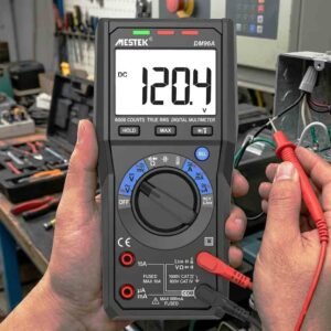
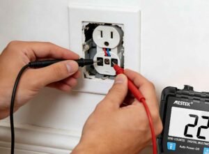
(1) Voltage test: Measures battery voltage, wall outlet power, or circuit board voltage.

(2) Current test: Identifies current in a circuit to troubleshoot.

(3) Resistance test: Checks for faults in resistors, wires, or electronic components.

(4) Diode test: Verifies diode functionality and polarity.

(5) Continuity test: Ensures wiring connections are intact, especially useful in automotive and home repairs.

When using a multimeter, you should always check whether the recent instrument tools are reliable. Otherwise, it will cause you trouble next time you use it, and misjudgment will cause maintenance and inspection difficulties.

Share our interesting knowledge and stories on social media

Have questions? Get a quote

Want to learn more? Click the button now.

More Posts>>>

Learn how to identify line and load wires safely. Use a multimeter or voltage tester to understand wiring differences and avoid hazards.

How to Identify Line and Load Wires Safely and Accurately

Understanding the difference between line and load wires is essential for anyone working with electrical systems. Whether you are installing a switch, replacing an outlet, or troubleshooting a circuit, correctly identifying line and load wires helps prevent electrical hazards, equipment damage, and wiring errors. What Are Line and Load Wires Before identifying wires, it is important to understand their roles in an electrical circuit. What Is a Line Wire? The line wire carries electrical power from the power source (such as a breaker panel) to a device. It is the incoming energized conductor that supplies voltage to switches, outlets, or

The image shows what an infrared thermal imager is.

What Is an Infrared Thermal Imaging Camera?

What if you could see heat instead of light? An infrared thermal imaging camera makes that possible. It detects invisible heat energy and turns it into a visual image of temperature differences. Unlike regular cameras that rely on visible light, thermal cameras work in total darkness. They can also operate in smoke, fog, and other low-visibility conditions. Thermal cameras are widely used in electrical inspections, industrial maintenance, and building diagnostics. They help professionals detect problems the naked eye cannot see, such as overheated wires or hidden heat loss. This guide explains how infrared thermal imaging works, what it can detect,

The picture depicts a worker using a multimeter to check for socket malfunctions.

How to Use a Multimeter to Check a Faulty Socket

Household sockets can stop working for several reasons, including loose wiring, a blown fuse, tripped circuit breakers, or worn out internal connections. Sometimes the problem is obvious, but often it requires proper testing to confirm whether the socket itself is faulty. That’s where understanding how to use a multimeter to check a faulty socket becomes essential. A multimeter is one of the easiest and most reliable tools for diagnosing electrical outlet problems. It can measure voltage, resistance, and continuity, helping you determine whether power is reaching the socket and whether the internal wiring is intact. This article explores everything you

The diagram illustrates the tools needed to test a relay using a multimeter.

How to Test a Relay with a Multimeter

Relays are small but essential components used in cars, appliances, HVAC systems, industrial equipment, and countless electronic devices. Their job is simple: they use a low power signal to safely and efficiently control a higher power circuit. Because relays switch electrical loads, they experience wear over time. Burnt contacts, damaged coils, or internal mechanical failure can cause them to stop working correctly. When a device suddenly stops turning on or won’t turn off, a faulty relay is often the cause. Fortunately, diagnosing a relay is not complicated. A digital multimeter is the easiest and most reliable tool for checking relay

Get more information

Scroll to Top