Household sockets can stop working for several reasons, including loose wiring, a blown fuse, tripped circuit breakers, or worn out internal connections. Sometimes the problem is obvious, but often it requires proper testing to confirm whether the socket itself is faulty. That’s where understanding how to use a multimeter to check a faulty socket becomes essential.
A multimeter is one of the easiest and most reliable tools for diagnosing electrical outlet problems. It can measure voltage, resistance, and continuity, helping you determine whether power is reaching the socket and whether the internal wiring is intact. This article explores everything you need to know about socket testing, from safety preparation to voltage and continuity checks.
What Is a Socket and How Does It Work?
A socket, also called an electrical outlet or receptacle, is a fixed device installed in walls that provides power to electrical appliances. It acts as the connection point between your home’s electrical wiring and the devices you plug in, such as lamps, chargers, or kitchen appliances.
A standard electrical socket contains three key terminals:
- Live (L): Carries alternating current (AC) from the electrical panel to the outlet.
- Neutral (N): Returns current back to the panel, completing the circuit.
- Earth (E) or Ground: Provides a safety path for fault current.
In the United States, standard outlets deliver 110–120 volts at 60 Hz. When you plug in a device, the Live wire supplies power, the Neutral wire completes the circuit, and the Earth wire protects you from electrical shock.
If the Live or Neutral wire becomes loose, your appliance may stop working or run intermittently. If the Earth wire disconnects, the outlet may still show voltage but it can become dangerous. That’s why proper electrical outlet testing must check both voltage and grounding.
Understanding these three connections ensures correct probe placement when performing a digital multimeter socket test.
What You Need to Test a Socket

Gather the following tools to perform proper socket testing with a multimeter:
- Digital Multimeter: A digital multimeter is the primary tool for measuring AC voltage, resistance and continuity. Choose a unit rated CAT II or CAT III for residential electrical testing. These safety ratings ensure the meter can handle voltage spikes common in household circuits.
- Screwdriver: If deeper inspection is needed, you may have to remove the socket faceplate. Use an insulated screwdriver to reduce shock risk.
- (Optional) Socket Tester: A plug in socket tester provides a quick initial check for reversed polarity, missing ground, or open neutral. However, it cannot replace a full digital multimeter socket test. Think of it as a preliminary tool rather than a complete diagnostic solution.
Having these tools ready ensures smooth and uninterrupted testing.
Safety Precautions Before Testing a Socket
Safety must always come first when working with electricity.
1) Always turn off the circuit breaker before doing a socket continuity test. Never assume the power is off. Switch the breaker fully to the OFF position and double check that no power is reaching the socket before touching it. Testing continuity on a live socket is very dangerous.
2) Continuity testing must only be done when the circuit is completely dead (no electricity flowing). If you use a multimeter in continuity mode on a live circuit, you can damage the meter and increase the risk of electric shock.
3) Voltage testing and continuity testing have different purposes and require opposite power conditions. Voltage testing is done with the power ON because you are measuring electrical voltage. Always be sure which test you are performing and whether the power should be on or off.
4) Wear rubber soled shoes and avoid working in wet or damp areas. Check your multimeter for cracks, exposed wires, or other damage before using it. Keep your hands dry at all times. Use insulated tools when handling the socket. Remove all plugs from the outlet before starting any testing.
Taking these precautions helps prevent electric shock and equipment damage.
How to Use a Multimeter to Check a Faulty Socket
Testing a socket requires a systematic approach that combines voltage measurements with continuity checks to diagnose common electrical faults.
Step 1: Identify the Socket Terminals
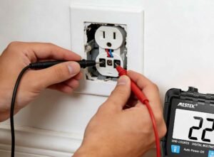
Locate the three socket terminals before beginning any digital multimeter socket test. In standard North American outlets, the smaller slot houses the Live wire, the larger slot contains the Neutral wire, and the round or D-shaped hole connects to the Earth wire. Correct identification prevents probe misplacement during socket voltage measurement and ensures accurate diagnostic results.
Step 2: Perform an AC Voltage Test Across the Socket
Set the multimeter to AC voltage mode (typically marked “V~” or “AC Voltage”) to begin the AC voltage test., using a range of 200V or higher. Insert the red probe into the Live slot and the black probe into the Neutral slot. A functional outlet displays between 110 and 120 volts.
Next, move the black probe to the Earth slot while keeping the red probe in Live. This reading should also show approximately 120V, confirming proper grounding. Low or zero readings indicate wiring faults, loose connections, or tripped breakers.
Step 3: Test Continuity with the Socket Powered Off
Switch off the circuit breaker before continuity testing. Set the multimeter to continuity or resistance mode. Test between Live and Neutral, Live and Earth, then Neutral and Earth. A beep or resistance reading below 50 ohms indicates continuity. An “OL” display signals infinite resistance. It means an open circuit or broken connection.
Step 4: Check for Loose Wires or Faulty Connections
Remove the socket cover and visually inspect the screw terminals. Gently probe each terminal with multimeter leads while observing for movement or poor contact. Burnt wires, blackened terminals, or loose screws confirm mechanical failures that voltage readings alone cannot detect.
Common Mistakes When Testing a Socket
Several testing mistakes compromise both accuracy and safety during electrical outlet testing. Avoid these common errors:
- Testing continuity on a live socket is dangerous.
- Misidentifying Live, Neutral, or Earth terminals.
- Using a multimeter without a proper safety rating (CAT II or CAT III).
- Assuming voltage readings alone prove the socket is safe.
Voltage presence does not guarantee proper grounding or stable wiring.
Can a Socket Be Faulty Even If the Multimeter Reads Correctly?
Yes, a socket can be faulty even if a multimeter shows the correct voltage.
Multimeters draw very little current, so they may display 120V or 230V even when the socket cannot handle a real load. Issues often appear only when an appliance is plugged in and starts drawing power.
Intermittent connections are a common cause. A loose or weakened terminal may briefly make contact with meter probes, allowing the outlet to pass a quick voltage or continuity test. However, once a device is connected, heat, vibration, or slight movement can break the connection, leading to flickering power or sudden failure.
Loose terminals can become weak due to aging, repeated use, or poor installation. Corrosion, partial shorts, or oxidized contacts can also create hidden faults. These problems increase resistance and cause voltage drops under load, even though no-load readings look normal.
That’s why physical inspection and proper load testing are just as important as multimeter checks.
FAQs
Can I test a socket without turning off the power?
Yes, voltage testing needs the socket to stay powered while measuring AC voltage between Live and Neutral. However, continuity testing must be performed with the breaker fully off. Testing continuity on a live circuit can damage the multimeter and create serious safety hazards.
What does OL mean when testing continuity?
OL (overload) indicates an open circuit or infinite resistance during a digital multimeter socket test. This reading confirms proper wire separation when the socket is unpowered. Between Live and Neutral terminals, OL shows that no short circuit exists. However, a beep or low resistance reading signals a fault requiring repair.
Can a socket appear fine but still be unsafe?
Yes, a socket may show correct voltage but still be dangerous under load. Loose or corroded terminals can cause overheating and voltage drops when appliances draw power. Damaged wires may pass basic tests yet fail during actual use.
How do I check if the grounding is working?
Set the multimeter to AC voltage mode and measure between Live and Earth terminals. The reading should be close to the Live Neutral voltage. A low or zero reading may indicate a grounding issue that needs immediate attention.
Conclusion
Testing a faulty socket with a multimeter requires understanding voltage and continuity measurements, proper terminal identification, and strict safety protocols. After all, distinguishing between live voltage testing and powered off continuity checks prevents equipment damage and serious injury.
Readers now possess the knowledge to diagnose socket problems accurately through systematic testing. Keep in mind that multimeter readings must be combined with physical inspection, as loose connections and corrosion can create intermittent failures that brief tests miss. Stay safe and test methodically.