What if you could see heat instead of light? An infrared thermal imaging camera makes that possible. It detects invisible heat energy and turns it into a visual image of temperature differences. Unlike regular cameras that rely on visible light, thermal cameras work in total darkness. They can also operate in smoke, fog, and other low-visibility conditions.
Thermal cameras are widely used in electrical inspections, industrial maintenance, and building diagnostics. They help professionals detect problems the naked eye cannot see, such as overheated wires or hidden heat loss. This guide explains how infrared thermal imaging works, what it can detect, where it is used, and its limitations.
What Is an Infrared Thermal Imaging Camera?
An infrared thermal imaging camera creates images using infrared radiation rather than visible light. Traditional cameras capture pictures within the visible light spectrum, typically ranging from 400 to 700 nanometers. Thermal cameras operate differently, detecting infrared wavelengths that extend up to 14,000 nanometers.
All objects emit infrared energy, commonly called a heat signature. The hotter an object becomes, the more thermal energy it emits. An infrared camera detects and measures this infrared energy from objects in its field of view. Regular cameras depend on reflected light to form images, but thermal cameras work by capturing emitted heat energy.
Here’s how it works at a high level:
- Objects emit infrared radiation based on their temperature.
- The infrared camera detects this radiation.
- The device converts temperature differences into a visual image called a thermal image.
In the thermal image, warmer areas may appear as bright colors like red or yellow, while cooler areas may appear blue or purple. These color patterns help users quickly identify temperature variations.
The key idea is simple: a thermal imaging camera turns invisible heat into a visible image
How Does Infrared Thermal Imaging Work?
The working process of an infrared thermal imaging camera involves several coordinated steps that happen within milliseconds.
Step 1: Capturing Infrared Radiation
The camera’s lens focuses infrared energy emitted by objects within its field of view. All objects emit this radiation as a function of their temperature. The optical system directs this energy toward the internal sensor.
Step 2: Detection by Sensor
A specialized sensor called a microbolometer detects the focused infrared radiation. This sensor consists of thousands of pixels arranged in a grid formation. Each pixel responds to the incoming thermal energy hitting its specific location.
Step 3: Signal Conversion
The microbolometer converts detected infrared radiation into electrical signals. The strength of each electrical signal corresponds directly to the amount of thermal energy received by that particular pixel.
Step 4: Image Processing
Built-in software processes these electrical signals. The processor assigns specific colors to different temperature values, creating a matrix of colors that represent the temperature distribution.
Step 5: Display
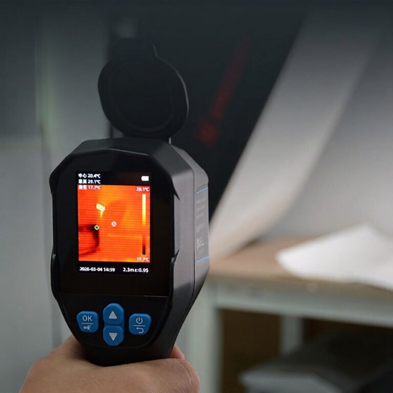
The final thermogram appears on the camera’s display in real time. This visual representation shows temperature variations across the entire scene, making invisible heat patterns visible and measurable.
Warmer areas often appear in red, yellow, or white. Cooler areas appear in blue or black. Some cameras offer multiple color palettes for better analysis.
Modern infrared cameras are highly sensitive. Some can detect temperature differences as small as 0.01°C. This level of detail allows users to identify early signs of overheating, insulation gaps, or mechanical wear.
The system works in darkness, bright sunlight, and challenging weather conditions.
What Can an Infrared Thermal Imaging Camera Detect?

Thermal imaging detection reveals issues that are often invisible during standard visual inspections. Identifying abnormal temperature patterns helps diagnose underlying problems before they become serious failures.
Here are common examples:
Electrical Systems
- Hot spots caused by loose connections or overloaded circuits
- High resistance at contact points produces localized heat
- Phase imbalances in power distribution systems
- Failing breakers, transformers, or switchgear
- Insulation breakdown in cables
Building Deficiencies
- Heat loss through walls, ceilings, and roofs
- Missing or damaged insulation
- Air leaks around windows and doors
- Moisture intrusion in walls or roofing materials
- Thermal bridges that increase energy loss
Industrial Equipment
- Overheating bearings, motors, pumps, and compressors
- Excessive friction in moving parts
- Misalignment in rotating machinery
- Abnormal process temperatures in furnaces or ovens
Additional Detection Capabilities
- Battery overheating in energy storage systems
- Uneven heat distribution in solar panels
- Gas leaks when using specialized optical gas imaging sensors
In all these cases, temperature variations act as early warning signals. Instead of waiting for equipment failure, technicians can address small issues before they escalate.
Common Applications of Infrared Thermal Imaging
Infrared thermography serves multiple industries where temperature monitoring prevents equipment failure and reduces operational costs.
The technology provides non-contact measurement capabilities across electrical, industrial, and building environments.
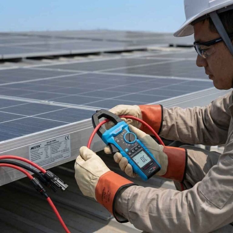
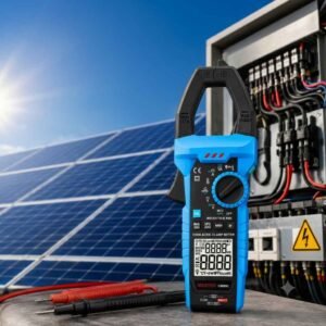
1) Electrical Inspections
Infrared thermography is widely used to inspect electrical panels, transformers, motor control centers, and distribution boards. Technicians scan equipment while it remains energized, identifying loose connections and overloaded circuits before they cause outages or fires.
2) Industrial Equipment Monitoring
Motors, bearings, and pumps generate specific heat patterns during normal operation. When temperatures rise unexpectedly, it may signal wear, friction, or alignment issues. Early detection prevents unplanned downtime and costly repairs.
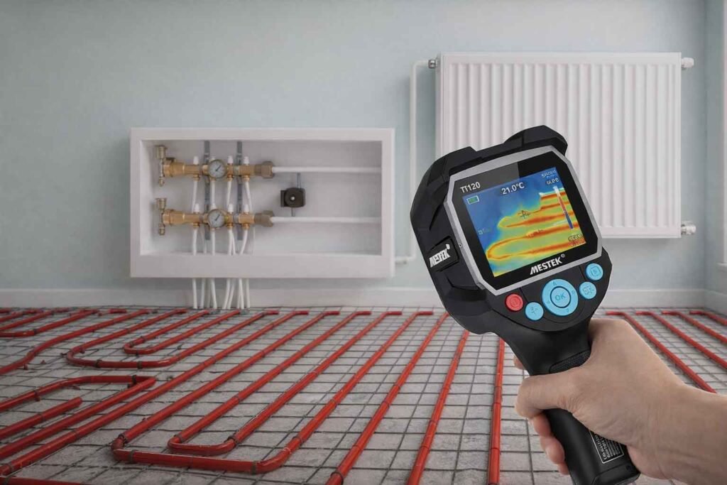
3) Building and Insulation Inspection
Buildings lose significant energy through poor insulation or air leakage. Thermal cameras reveal hidden insulation gaps and HVAC inefficiencies. They also help detect moisture, which alters thermal behavior compared to dry materials.
4) Predictive Maintenance
Regular thermal inspections allow organizations to shift from reactive to predictive maintenance. Instead of fixing equipment after failure, maintenance teams schedule repairs based on early heat anomalies. This reduces downtime and extends asset life.
Advantages of Infrared Thermal Imaging Cameras
The benefits of thermal imaging make it a valuable diagnostic tool in many industries.
1) Non-Contact Measurement
Infrared inspection allows technicians to measure temperature without touching the object. This improves safety when working near high-voltage systems, rotating machinery, extremely hot surfaces and hazardous chemicals.
2) Improved Safety
Thermal imaging keeps inspectors at a safe distance. There is no need to open energized panels or physically contact hot components, reducing the risk of electrical shock or burns.
3) Faster Inspections
Thermal cameras capture thousands of temperature data points simultaneously. Large areas, such as entire walls or electrical panels, can be scanned within minutes.
4) Real-Time Results
Results appear instantly on the screen. Technicians can verify repairs immediately after maintenance work is completed.
5) Early Problem Detection
Heat often develops before visible damage occurs. Facilities can prevent catastrophic failures, reduce downtime, extend equipment life and lower maintenance costs by identifying temperature changes early. Overall, infrared inspection improves efficiency while reducing operational risk.
Limitations of Infrared Thermal Imaging
Despite its strengths, thermal imaging has important limitations.
- Cannot See Through Solid Objects: Thermal cameras measure only surface temperatures. They cannot see through walls, concrete, or metal. When aimed at a wall, the camera detects the wall’s surface temperature not what is behind it. Glass is another barrier. Infrared radiation does not pass through standard glass, so the camera measures the temperature of the glass itself.
- Environmental Influences: Several factors affect infrared camera accuracy, including ambient temperature, airflow and wind, humidity and rain or fog. Reflective surfaces like polished metal may reflect surrounding heat, causing misleading readings.
- Surface Temperature vs Internal Temperature: Thermal cameras detect surface heat, which may not always match internal conditions. For example, airflow patterns can influence surface temperature without indicating structural damage.
- Requires Proper Interpretation: Thermal imaging is a diagnostic aid, not a standalone solution. Accurate analysis often requires training and complementary tools such as moisture meters or electrical testers. Used correctly, thermal imaging enhances inspections. Used alone without context, it may lead to incomplete conclusions.
Infrared Thermal Imaging vs Traditional Inspection Methods
Traditional inspections rely on visual checks and point-based tools such as moisture meters, voltage testers, and contact thermometers. These methods can identify visible damage, such as cracks or corrosion, but hidden problems behind walls or within sealed equipment often go unnoticed. They may also require dismantling components, making inspections time-consuming and disruptive.
Spot temperature devices, including infrared thermometers, measure only one point at a time. Inspectors must scan each component individually, which increases labor and the risk of missing developing hot spots. In contrast, thermal imaging cameras capture thousands of temperature points simultaneously, providing a full-field view in seconds.
Safety is another key difference. Traditional methods often require close proximity to energized systems, while thermal imaging allows safe, non-contact inspections during normal operation.
Both approaches are complementary: visual tools verify details, while thermal imaging reveals hidden temperature anomalies for a more complete assessment.
FAQs
1. Can an infrared thermal imaging camera see through walls?
No. Thermal cameras cannot see through solid objects like walls. They detect surface temperature differences. However, they can reveal hidden issues such as moisture or insulation problems because those issues affect surface temperature.
2. Are infrared thermal cameras safe to use?
Yes. Thermal cameras are completely safe. They do not emit radiation. They only detect naturally emitted infrared energy from objects.
3. What is the difference between night vision and thermal imaging?
Night vision amplifies visible light, while thermal imaging detects heat. Thermal cameras work in total darkness and do not require any light source.
4. How accurate are infrared thermal imaging cameras?
Accuracy depends on the model and calibration. Professional-grade cameras typically offer ±2°C or ±2% accuracy, while consumer models may have slightly lower precision.
Conclusion
Infrared thermal imaging cameras provide a powerful way to detect hidden problems. They reveal overheating components, insulation failures, and electrical faults before serious damage occurs. This allows facilities to reduce downtime and extend equipment life.
However, understanding both strengths and limitations is essential. Thermal imaging works best when combined with traditional inspection methods. With proper training and consistent use, it transforms maintenance from reactive to proactive. The result is improved safety, lower costs, and more reliable operations.