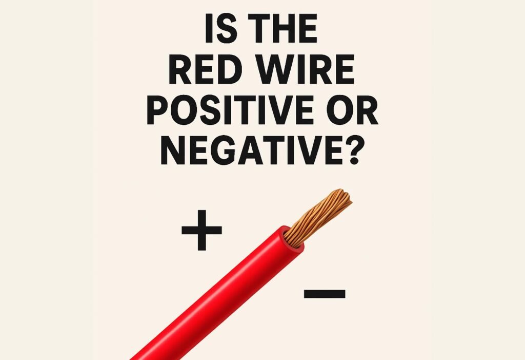
When working with electrical wiring, one of the most common questions people ask is: “Is the red wire positive or negative?”
Although color codes can make wiring easier to identify, not all systems follow the same standard. Understanding what each wire color represents is essential for safety and accuracy—especially when working with DC circuits, automotive systems, or HVAC controls.
Understanding Wire Color Codes
In most DC electrical systems, such as automotive and battery-powered devices, the red wire is positive (+) and the black wire is negative (–).
This convention helps prevent wiring mistakes and short circuits when connecting components.However, this rule doesn’t apply to every system.In AC (alternating current) wiring, the color coding can vary depending on the region or electrical standard.
| Region | Live (Hot) | Neutral |
| North America | Black / Red | White |
| Europe | Brown | Blue |
| Asia (IEC) | Red / Brown | Black / Blue |
So while red often indicates a live or positive conductor, it’s not universal. Always verify before connecting wires—especially in international or mixed-voltage systems.
How to Identify Positive and Negative Wires with a Multimeter
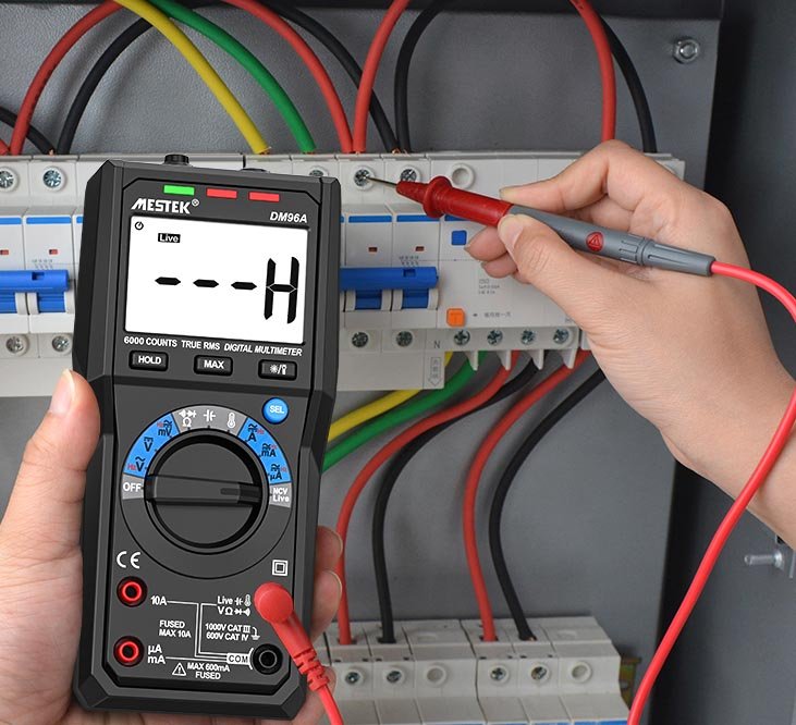
The most reliable way to determine polarity isn’t by color—it’s by measurement.
A digital multimeter can quickly show which wire carries positive or negative voltage.
1.Set the multimeter to DC voltage (V⎓).
Select a range higher than your expected voltage (e.g., 20V for a 12V circuit).
2.Connect the probes.
The black probe goes to the COM port.
The red probe goes to the VΩmA port.
3.Touch the probes to the wires.
If the reading shows a positive value, the red probe is touching the positive wire.
If the reading shows a negative value, the red probe is on the negative wire.
4.Reverse the probes to confirm
A stable reading helps verify polarity and ensure safe wiring connections.
This quick test is especially useful in automotive diagnostics, solar panel setups, and DC power circuits.
Common Mistakes When Reading Wire Colors
Even though red and black are commonly associated with positive and negative, there are situations where this rule fails.
- Switch legs in home wiring may use red for secondary live connections, not positive.
- Lighting circuits can have red wires that are switched hot, not always carrying constant voltage.
- Old installations or DIY repairs might use inconsistent color codes.
Red and Black Wire in Different Systems
| System | Red Wire | Black Wire | Note |
| DC / Battery | Positive (+) | Negative (–) | Common in vehicles and electronics |
| AC (North America) | Live (hot) | Live (hot) | Red often used for second hot wire |
| HVAC Systems | 24V Power (R) | Common (C) | Red = R terminal, Black = C terminal |
| Audio Wiring | Right Channel (+) | Left Channel (–) | May vary by manufacturer |
Knowing these standards helps avoid costly errors, equipment damage, or short circuits.
FAQs
Usually in DC circuits, yes—but not always in AC or control systems.
Use a multimeter to test for voltage polarity. Never guess by appearance.
In rare cases, yes—especially in multi-phase AC wiring. Always confirm using proper tools.
Final Thoughts
In most DC and low-voltage systems, red typically indicates positive and black indicates negative, though exceptions can occur in AC circuits and complex control systems.
The most reliable way to confirm polarity is by testing with a multimeter before making any connections, which helps prevent electrical faults, saves time, and ensures safe operation across all electrical projects.