Capacitors are in almost every electronic device. They store and release energy, smooth out signals, and keep power supply lines stable. When a capacitor fails, circuits will malfunction, power supplies will become unstable and sensitive devices will stop working. For technicians, DIY electronics hobbyists and engineers, knowing how to test a capacitor with a multimeter is a must have skill.
Measuring capacitance is important because it verifies if a capacitor is still within its rated tolerance. Over time, heat, voltage surges or age degrade the dielectric of a capacitor reducing performance or causing failure. A multimeter, especially one with capacitance measurement function, is a practical way to test capacitors in and out of circuits. This article explores the capacitor basics, preparation steps, safety measures, tools required and several practical methods to test a capacitor with a multimeter.
Before You Begin: Safety First
Safety first when testing capacitors with a multimeter. Capacitors store energy even after power is disconnected, they can be dangerous if not handled properly.
Why Discharge Capacitors First
Capacitors can retain a charge for a long time and can deliver nasty shocks or damage your multimeter. Industry standards require capacitors to have internal discharge devices to reduce voltage to below 50V within 1 minute for 600VAC capacitors and within 5 minutes for those above 600V. IEC 60831 standards require discharge to less than 75V within 3 minutes to prevent accidental injury.
Besides personal safety, discharging prevents damage to your multimeter and ensures accurate readings. A charged capacitor can give false readings or worse damage your testing equipment.
Safe Discharge Methods
The safest way to discharge a capacitor is by connecting resistors across its terminals. For safety, choose a resistor with the right resistance (typically 5 to 50 ohms per volt of the capacitor’s working voltage) and sufficient wattage rating (calculated using P = V²/R).
Never short circuit the capacitor with a screwdriver as this can cause sparks, arcing, terminal damage or even small explosions. A proper discharge tool can be made using high wattage resistors connected to insulated probes or clips. Commercial discharge tools are also available for frequent users.
Visual Inspection is Important
Before you start electrical testing, do a visual inspection of the capacitor. Check for bulges or swelling at the top, leaking fluid near the battery ends or body, cracks in the case, and any burn marks or discoloration.
These signs indicate the capacitor is already faulty and should be replaced immediately. Even a good looking capacitor can be bad; so electrical testing is still necessary regardless of appearance. Always wear the right safety gear including insulating gloves rated for the voltage you’re working with and safety glasses to protect against arc flash. These simple precautions can prevent serious injury when working with capacitors.
Tools Required for Capacitor Testing
Accurate capacitor testing requires the right tools to ensure precise measurements and operator safety. At the heart of this toolkit is a digital multimeter with capacitance functionality.
Modern DMMs have advantages over analog meters. By converting analog signals to digital data, they give precise readings on an easy to read display. Many quality meters include a dedicated capacitance mode, usually marked with the capacitor symbol (-||-). In this mode, the meter sends a small current into the capacitor, measures the voltage, and then automatically shows the capacitance value.
Additional Accessories
- Test Leads: Good quality test leads are important for accurate results. It has sharp gold plated tips for precise contact, double layered insulation for safety and durability and flexible heat resistant design for comfortable handling.
- Alligator Clips: These are great for holding connections steady especially for small or surface mounted capacitors. It frees up your hands and makes testing more stable.
- Insulating Gloves: Safety is non-negotiable. Insulating gloves protect you from accidental contact with charged capacitors. Choose gloves rated for the voltage you’re working with Class 00 (up to 500V AC) or Class 0 (up to 1000V AC).
- Tweezers Probes: These special probes help test small capacitors on circuit boards. They are shaped like tweezers making it easy to measure small components with one hand.
- Discharge Device: Before testing always discharge a capacitor safely. A simple discharge tool can be made with a resistor (15–20k Ohm) connected to insulated wires. This prevents shocks and protects your equipment.
Methods to Test a Capacitor
Testing a capacitor is necessary to ensure it works in electronic circuits. Capacitors can degrade or fail over time and cause short circuits, open circuits or reduced efficiency. Below are some methods to test a capacitor using different modes of a multimeter or physical inspection.
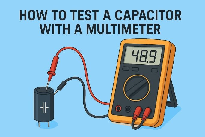
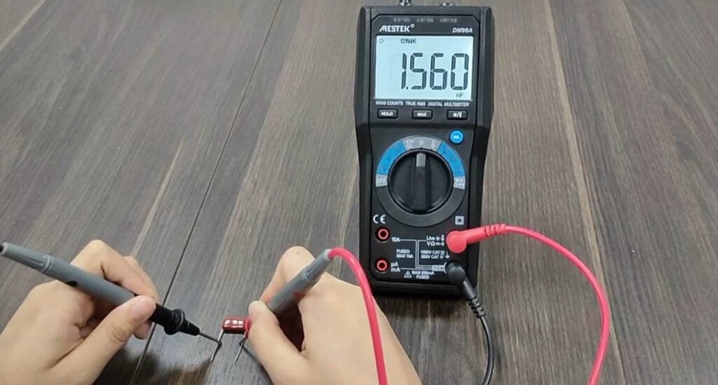
1. Direct Measurement with Capacitance Mode
Most digital multimeters have a built-in mode for measuring capacitance (look for the capacitor symbol on the dial). This is the easiest and most common way to test a capacitor. To check if a capacitor is working, switch the multimeter to capacitance mode and follow these steps:
- Remove the capacitor from the board.
- Discharge the capacitor by briefly touching its leads to a resistor. This protects your meter from damage.
- Connect the capacitor to the multimeter by placing the red probe on the positive (long lead) and the black probe on the negative (short lead).
- Turn the multimeter to capacitance mode (the setting with the capacitor symbol).
- Read the value: check the number shown on the screen and compare it with the value written on the capacitor.
If the reading is within about 10–20% of the printed value, the capacitor is usually fine. If it’s much higher or lower, the capacitor is most likely bad and should be replaced.
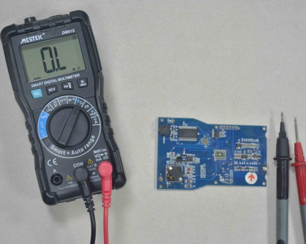
2. Using Resistance (Ohm) Mode
A multimeter in resistance mode can also determine if a capacitor is working. The test is based on the capacitor’s ability to charge when current flows through it. Follow these steps:
- Remove the capacitor from the circuit board.
- Discharge the capacitor completely by connecting its leads across a resistor. Once discharged, take it out for testing.
- Set the multimeter to the OHM (Ω) range, for example, 1kΩ.
- To test a capacitor with a digital multimeter (DMM), connect the probes to its positive and negative terminals.
Using a Digital Multimeter (DMM): The meter applies a small current, causing the capacitor to begin charging. The display should show resistance values that gradually rise from low to very high (approaching infinity). If this happens, it means the capacitor is charging normally and is in good condition. If the display stays at a low resistance, the capacitor is shorted. If the display stays at infinity (very high resistance), the capacitor is open and should be replaced.
Using an Analog Multimeter: The needle should swing from low resistance to high resistance as the capacitor charges, which means it is working correctly. If the needle stays low and doesn’t rise, the capacitor is defective and has a short circuit. If the needle remains at high resistance, the capacitor is open and needs replacement.
3. Voltage Response Method
This method tests the capacitor’s ability to hold charge. You can also test a capacitor with the voltmeter function of a multimeter. Follow these steps:
- Check the rated voltage of the capacitor.
- Charge the capacitor to a safe voltage below its maximum rating (for example, charge to 3V for a 35V capacitor is sufficient). Connect the battery’s positive end to the longer leg of the capacitor and the negative end to the shorter leg.
- Then place the multimeter probes on the capacitor — red on positive and black on negative.
- Set the multimeter to DC voltage mode. The display should show a voltage reading close to the value to which the capacitor was charged. If it does, the capacitor is good. If not, the capacitor is bad.
- Take the reading quickly. Capacitors start to discharge once disconnected from the power source which can cause the reading to drop and lead to an incorrect conclusion.
4. Testing capacitors using the multimeter’s continuity mode
After discharging the capacitor safely, set your multimeter to continuity mode. Connect the probes to the capacitor terminals. A good capacitor will trigger a beep briefly and then fade as the capacitor charges. If the beeping does not stop, it indicates that the capacitor is shorted. If no beep occurs at all, the capacitor is open. To test step by step:
- Remove the capacitor from the circuit board.
- Fully discharge it by connecting across a resistor, then detach for testing.
- Connect the red probe to the capacitor’s positive side and the black probe to the negative side.
- Rotate the multimeter knob to continuity mode (look for the wave-like symbol).
- If the multimeter beeps continuously (or the LED stays on), the capacitor is shorted.
- If it doesn’t beep, the capacitor is open.
- If the multimeter beeps briefly (or LED lights up) and then stops, the capacitor is good.
5. RC Time Constant Estimation
The time constant of a circuit is how long a capacitor takes to charge up to about 63% of the applied voltage through a resistor. The formula is τ = R × C, where τ (tau) is the time constant, R is the resistance in ohms, and C is the capacitance in farads.
To test a capacitor using the time constant method:
- Remove the capacitor from the circuit board.
- Fully discharge it by connecting it across a resistor.
- Connect the capacitor in line with a resistor of known value.
- Attach the setup to the multimeter probes and switch the meter to DC voltage mode.
- Apply a known voltage (e.g., 10V) across the RC combination.
- Read the capacitor voltage on the multimeter.
- Use a stopwatch to measure how long it takes for the voltage to reach 63% of the supply voltage (for example, 6.32V if using 10V).
- Find the capacitance with the formula C = τ / R.
- Match this result with the value written on the capacitor.
- If the two values are nearly the same, the capacitor is good.
- If there is a large difference, the capacitor is bad and should be replaced.
6. Visual and Physical Inspection
Sometimes faults in capacitors are visible without any instrument testing. Common signs a capacitor has failed include a bulging top or bottom, leaking fluid, cracks in ceramic types, or broken leads. Electrolytic capacitors develop a swollen or lifted case when gas pressure builds inside during failure.
Burn marks or damaged casing also indicate that the capacitor has failed. Visual inspection should be the first step before electrical testing because damaged capacitors often pose risks to surrounding components. If any of these signs are observed, the capacitor must be replaced immediately as it can no longer be relied upon. This is the quickest method but only works for visibly damaged parts.
FAQs
1) Can I measure capacitance in a circuit?
In most cases it’s not recommended to measure capacitors in circuits. Other components can interfere with the readings and give inaccurate results. To get reliable measurements, you need to disconnect at least one side of the capacitor from the circuit. However, there are some advanced techniques like series methods to measure small capacitors in parallel.
2) How accurate is a multimeter in measuring capacitance?
Standard digital multimeters have moderate accuracy for capacitance readings. But their accuracy can’t match dedicated capacitance or LCR meters. Many multimeters show significant errors when measuring small capacity capacitors below 50pF and readings for capacitors under 20pF are practically unreliable.
3) How can I tell if a capacitor is bad?
A capacitor is bad if its measured value is far from the rated value. Generally a 10-20% variation is considered good. Visual inspection may show bulging tops, electrolyte leakage (brown crust) or cracks in the casing. Testing with a multimeter in capacitance mode will show much lower readings for bad capacitors.
4) What is the difference between analog and digital meters?
Digital multimeters display exact numerical values with higher precision, analog meters use needle movement and require manual interpretation. So digital meters are more accurate for capacitance testing. But analog meters respond faster to changes and are useful for observing charging patterns.
Conclusion
Testing capacitors requires knowledge and caution, safety first. Always discharge capacitors before handling and use protective gear to avoid shocks. A digital multimeter with capacitance mode will give the most accurate results, but resistance, continuity or time constant methods can be useful alternatives. The first step is a visual check, since bulging, leaks, or damage usually indicate failure. Correctly interpreting the measurements ensures accurate troubleshooting. Master these techniques and you’ll be able to quickly identify bad capacitors, maintain circuits and restore functionality safely and effectively.